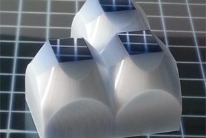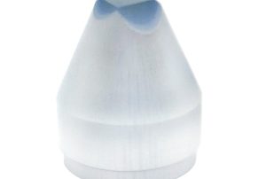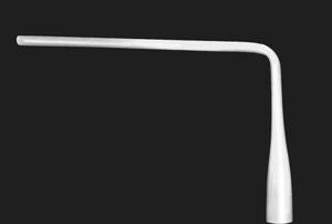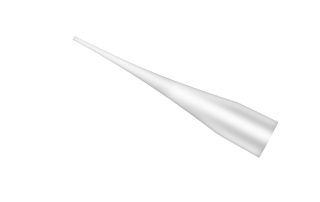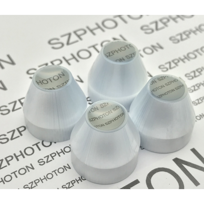
Fiber Optic Taper
Fiber Pitch (Small End):
>4um~12um or others
EMA Absorber:
Interstitial / Without
Resolution:
≥100lp/mm
Coefficient expansion at (20~300℃):
60~90 x10⁻⁷/ ℃
Collimating Transmittance:
>70%
Numerical Aperture (Small End):
1.0
Magnification Ratio:
1:2 / 1:3 / 1:4 or customized
Core/Clad Ratio:
60/40 ~75/25 or others
Vacuum Tightness:
<10⁻¹² Pa.m³/s
Diffuse Light Transmittance:
>65%
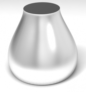
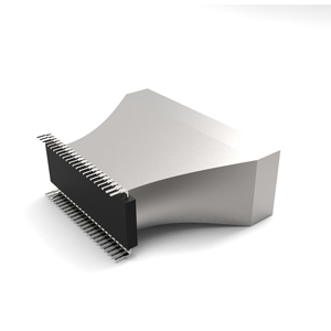
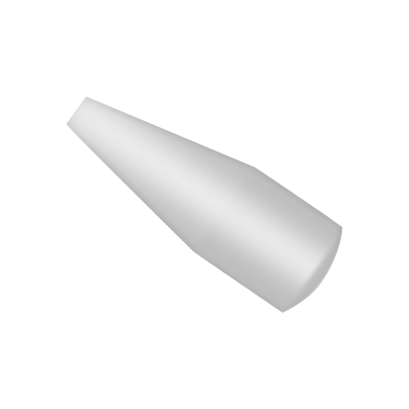
The fiber optic tapers provide a method of minify or magnify an image with minimum distortion in image transfer applications.
All tapers are fabricated to customer specific requirements and can be machined into configurations from round to round, square to square, round to square or rectangular.
Features:
- Magnification (Minification) ratio up to 4:1
- Resolution up to 125 lp/mm (Small end)
- No focusing distance is required, Enable a higher coupling efficiency.
- Expand photosensitive area of CMOS/CCD
- Compact Design, easier to integrate.
Application:
- Radiography
- Fluorescence
- Imaging
- Light Field Camera
wdt_ID Attribute Value
9
Fiber Diameter (Small End)
>4um~12um or others
10
Numerical Aperture (N.A) Small End
1.0
11
Resolution
≥100lp/mm
12
Magnification Ratio
1:2 / 1:3 / 1:4 or customized
13
Core / Clad Ratio
60/40~ 75/25 or others
14
EMA Absorber
Interstitial / Without
15
Coefficient expansion at (20~300℃)
60~90 x10⁻⁷/ ℃
16
Vacuum tightness:
<10⁻¹² Pa.m³/s
17
Collimating transmittance
>70%
18
Diffuse light transmittance
>65%
19
Transmission range
VIS 400nm~900 nm
20
Gross distortion
<0.5% of effective area
21
Shear distortion
≤30um
22
Frame run out
≤200um
23
Barrel/pincushion
<3% of effective area
Following explanation to the terms that you should know about Fiber Optic Tapers.
1.Fiber Diameter (Pitch)
Diameter of a fiber strand / Distance between fiber centering
2.Numerical Aperture
Capability of light gathering of fiber optic components.
3.Resolution
The measure of how closely lines can be resolved in one milimeter
4.EMA
Extra Mural Absorption(EMA) are small black fibers that inserted between 2 fiber strands. Which will absorb stray light between fibers.
5.Core
The transmitting part of the fiber optic wave guide. (Core usually has higher refraction index than cladding)
6.Cladding
The cover outside core, cladding has a lower index of refraction than core.
7.Packing Fraction
Ratio of Core area to Total area, this will shows the light transmission efficiency of the component.
9.Transmission
Comparison between Output light intensity and Input Light Intensity
10.Optical Crosstalk
The light escape from one fiber strand and get into another fiber.
11.Blemish
Blemishes are the area where transmission is reduced. Blemish is caused by contaminants along in the fibers.
12.Chickenwire
Chicken wire appear likes a black line on the components. The result of chicken wire is due to mal-control of temperature or pressure during the procedure.
13.Coefficient Thermal Expansion
CTE defined as the changing of dimension when the fiber components exposed to changing temperature environment
14.Shear Distortion
Shear distortion is cause by the misalignment of fiber during fusion process.
|
|
15.Gross Distortion
Gross Distortion is cause by in-proper Temperature/Pressure and Material input procedure.
 |
Fiber Optic Taper (Round to Round) / (Round to Square)
wdt_ID Model Type Magnification Ratio Samll End(mm) Large end(mm) NA(Small end) CCD/CMOS Matched
7
FOT11-2.3
2.3X
dia. 11
dia. 25
1
2/3" CCD
8
FOT18-3
3X
dia. 6
dia. 18
1
1/3" CCD
9
FOT10-2
2X
dia. 10
dia. 20
1
1/1.6" CCD
10
FOT13.7-3
3X
dia. 13.7
dia. 41
1
2/3“ CCD
11
FOT23-3
3X
dia. 23
dia. 72
1
4/3" CCD
12
FOT7x5-1.5
1.5X
7x5
dia. 20.0
1
1/2" CCD
13
FOT7.5x5-2.25
2.25X
7.5x5
dia. 20.0
1
1/2" CCD
14
FOT6.4x4.8-1.85
1.85X
6.4x4.8
dia. 15.5
1
1/2" CCD
15
FOT6.4x4.8-2
2X
6.4x4.8
dia. 17.5
1
1/2" CCD
16
FOT6.4x4.8-3.12
3.12X
6.4x4.8
dia. 25.0
1
1/2" CCD
| wdt_ID | Model Type | Magnification Ratio | Samll End(mm) | Large end(mm) | NA(Small end) | CCD/CMOS Matched |
|---|---|---|---|---|---|---|
| 7 | FOT11-2.3 | 2.3X | dia. 11 | dia. 25 | 1 | 2/3" CCD |
| 8 | FOT18-3 | 3X | dia. 6 | dia. 18 | 1 | 1/3" CCD |
| 9 | FOT10-2 | 2X | dia. 10 | dia. 20 | 1 | 1/1.6" CCD |
| 10 | FOT13.7-3 | 3X | dia. 13.7 | dia. 41 | 1 | 2/3“ CCD |
| 11 | FOT23-3 | 3X | dia. 23 | dia. 72 | 1 | 4/3" CCD |
| 12 | FOT7x5-1.5 | 1.5X | 7x5 | dia. 20.0 | 1 | 1/2" CCD |
| 13 | FOT7.5x5-2.25 | 2.25X | 7.5x5 | dia. 20.0 | 1 | 1/2" CCD |
| 14 | FOT6.4x4.8-1.85 | 1.85X | 6.4x4.8 | dia. 15.5 | 1 | 1/2" CCD |
| 15 | FOT6.4x4.8-2 | 2X | 6.4x4.8 | dia. 17.5 | 1 | 1/2" CCD |
| 16 | FOT6.4x4.8-3.12 | 3.12X | 6.4x4.8 | dia. 25.0 | 1 | 1/2" CCD |

